
반응형
RFID는 Radio Frequency Identification의 약자로 무선 주파수를 이용하여 RFID태그와 리더기 간에 데이터를 교환하는 장치입니다. NFC통신 방식을 사용하며 13.56MHz의 주파수 대역을 사용하여 10cm이내 가까운 거리의 비접촉 통신으로 작동합니다. 보통 우리가 실생활에 자주 사용하는 교통카드, 신분증, 출입문 카드 등에 사용되고 있습니다.
여기서 사용하는 RC522모듈은 RFID를 읽고 기록하는 본체와 RFID 고유 데이터가 내장된 카드키와 열쇠고리가 포함되어 있습니다.
- 동작전압 : DC 3.3V
- 동작전류 : 13~26 mA
- 동작주파수 : 13.56MHz

1) 카드 고유번호 읽기
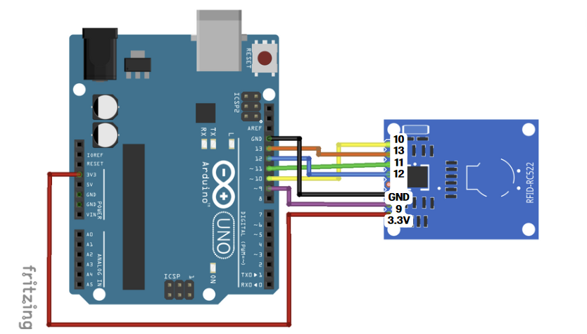
회로도
소스코드
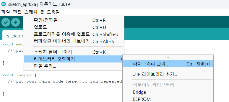
스케치-> 라이브러리 포함하기->라이브러리 관리
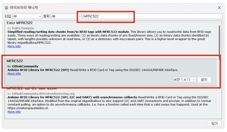
'MFRC522' 검색하여 설치
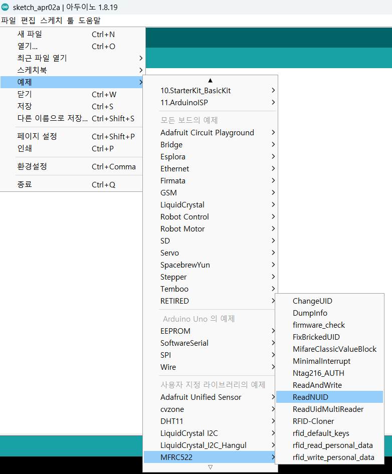
- 예제->MFRC522->ReadNUID 선택합니다.
/*
 * --------------------------------------------------------------------------------------------------------------------
 * Example sketch/program showing how to read new NUID from a PICC to serial.
 * --------------------------------------------------------------------------------------------------------------------
 * This is a MFRC522 library example; for further details and other examples see: https://github.com/miguelbalboa/rfid
 *
 * Example sketch/program showing how to the read data from a PICC (that is: a RFID Tag or Card) using a MFRC522 based RFID
 * Reader on the Arduino SPI interface.
 *
 * When the Arduino and the MFRC522 module are connected (see the pin layout below), load this sketch into Arduino IDE
 * then verify/compile and upload it. To see the output: use Tools, Serial Monitor of the IDE (hit Ctrl+Shft+M). When
 * you present a PICC (that is: a RFID Tag or Card) at reading distance of the MFRC522 Reader/PCD, the serial output
 * will show the type, and the NUID if a new card has been detected. Note: you may see "Timeout in communication" messages
 * when removing the PICC from reading distance too early.
 *
 * @license Released into the public domain.
 *
 * Typical pin layout used:
 * -----------------------------------------------------------------------------------------
 *             MFRC522      Arduino       Arduino   Arduino    Arduino          Arduino
 *             Reader/PCD   Uno/101       Mega      Nano v3    Leonardo/Micro   Pro Micro
 * Signal      Pin          Pin           Pin       Pin        Pin              Pin
 * -----------------------------------------------------------------------------------------
 * RST/Reset   RST          9             5         D9         RESET/ICSP-5     RST
 * SPI SS      SDA(SS)      10            53        D10        10               10
 * SPI MOSI    MOSI         11 / ICSP-4   51        D11        ICSP-4           16
 * SPI MISO    MISO         12 / ICSP-1   50        D12        ICSP-1           14
 * SPI SCK     SCK          13 / ICSP-3   52        D13        ICSP-3           15
 *
 * More pin layouts for other boards can be found here: https://github.com/miguelbalboa/rfid#pin-layout
 */

#include <SPI.h>
#include <MFRC522.h>

#define SS_PIN 10
#define RST_PIN 9

MFRC522 rfid(SS_PIN, RST_PIN); // Instance of the class

MFRC522::MIFARE_Key key;

// Init array that will store new NUID
byte nuidPICC[4];

void setup() {
  Serial.begin(9600);
  SPI.begin(); // Init SPI bus
  rfid.PCD_Init(); // Init MFRC522

  for (byte i = 0; i < 6; i++) {
    key.keyByte[i] = 0xFF;
  }

  Serial.println(F("This code scan the MIFARE Classsic NUID."));
  Serial.print(F("Using the following key:"));
  printHex(key.keyByte, MFRC522::MF_KEY_SIZE);
}

void loop() {

  // Reset the loop if no new card present on the sensor/reader. This saves the entire process when idle.
  if ( ! rfid.PICC_IsNewCardPresent())
    return;

  // Verify if the NUID has been readed
  if ( ! rfid.PICC_ReadCardSerial())
    return;

  Serial.print(F("PICC type: "));
  MFRC522::PICC_Type piccType = rfid.PICC_GetType(rfid.uid.sak);
  Serial.println(rfid.PICC_GetTypeName(piccType));

  // Check is the PICC of Classic MIFARE type
  if (piccType != MFRC522::PICC_TYPE_MIFARE_MINI &&
    piccType != MFRC522::PICC_TYPE_MIFARE_1K &&
    piccType != MFRC522::PICC_TYPE_MIFARE_4K) {
    Serial.println(F("Your tag is not of type MIFARE Classic."));
    return;
  }

  if (rfid.uid.uidByte[0] != nuidPICC[0] ||
    rfid.uid.uidByte[1] != nuidPICC[1] ||
    rfid.uid.uidByte[2] != nuidPICC[2] ||
    rfid.uid.uidByte[3] != nuidPICC[3] ) {
    Serial.println(F("A new card has been detected."));

    // Store NUID into nuidPICC array
    for (byte i = 0; i < 4; i++) {
      nuidPICC[i] = rfid.uid.uidByte[i];
    }

    Serial.println(F("The NUID tag is:"));
    Serial.print(F("In hex: "));
    printHex(rfid.uid.uidByte, rfid.uid.size);
    Serial.println();
    Serial.print(F("In dec: "));
    printDec(rfid.uid.uidByte, rfid.uid.size);
    Serial.println();
  }
  else Serial.println(F("Card read previously."));

  // Halt PICC
  rfid.PICC_HaltA();

  // Stop encryption on PCD
  rfid.PCD_StopCrypto1();
}


/**
 * Helper routine to dump a byte array as hex values to Serial.
 */
void printHex(byte *buffer, byte bufferSize) {
  for (byte i = 0; i < bufferSize; i++) {
    Serial.print(buffer[i] < 0x10 ? " 0" : " ");
    Serial.print(buffer[i], HEX);
  }
}

/**
 * Helper routine to dump a byte array as dec values to Serial.
 */
void printDec(byte *buffer, byte bufferSize) {
  for (byte i = 0; i < bufferSize; i++) {
    Serial.print(' ');
    Serial.print(buffer[i], DEC);
  }
}
[실행결과]
소스코드를 업로드한 후 카드키 또는 열쇠키를 본체에 대면 고유번호가 시리얼 모니터에 출력됩니다.

- 여기서 16진수 hex: "23 57 B8 97" 이 아이디로 사용됩니다.
2) 도어락 만들기
회로도

소스코드
#include <SPI.h>
#include <MFRC522.h>

#define SS_PIN 10
#define RST_PIN 9

MFRC522 rfid(SS_PIN, RST_PIN); // Instance of the class

#include <Servo.h>
#define servoPin 3
Servo servo;

int RLED=7;
int GLED=6;
int BLED=5;

void setup() {
  Serial.begin(9600);
  pinMode(RLED, OUTPUT);
  pinMode(GLED, OUTPUT);
  pinMode(BLED, OUTPUT);
  servo.attach(servoPin);
  servo.write(0);

  SPI.begin(); // Init SPI bus
  rfid.PCD_Init(); // Init MFRC522

  Serial.println(F("Ready to read your card"));
}

void loop() {
    // 새로운 카드 접촉이 있을 때만 다음 단계로 넘어 가도록 함
  if ( ! rfid.PICC_IsNewCardPresent())
    return;

  // 카드가 제대로 읽히면 다음 단계로 넘어감
  if ( ! rfid.PICC_ReadCardSerial())
    return;

  // 현재 접촉 되는 카드 타입을 읽어와 모니터에 표시함
  Serial.print("UID tag :");
  String content="";
  byte letter;
  for (byte i=0; i<rfid.uid.size; i++)  {
    Serial.print(rfid.uid.uidByte[i] < 0x10? "0": " ");
    Serial.print(rfid.uid.uidByte[i], HEX);
    content.concat(String(rfid.uid.uidByte[i] < 0x10? "0" : " "));
    content.concat(String(rfid.uid.uidByte[i], HEX));
  }
  Serial.println();
  Serial.print("Message: ");
  content.toUpperCase();

  // UID값이 아래 값과 같으면 승인 처리
  if (content.substring(1) == "23 57 B8 97") { // 자신의 UID로 수정(16진수Hex코드)
    // 인증이 되면 Green LED와 함께 서보모터를 작동시킨다.
    Serial.println("Authorized access");
    Serial.println();
    digitalWrite(GLED,HIGH);
    servo.write(180); // 서보모터의 각도를 변경한다.
    delay(3000); // 서보 모터의 각도가 변하는 것을 기다려 준다
    servo.write(0);  // 시간지연 후 문을 닫는다.
    digitalWrite(GLED,LOW);
  }
  else {   // 승인 목록에 없는 UID 처리는
    Serial.println(" Access denied");
    digitalWrite(RLED, HIGH);
    delay(3000);
    digitalWrite(RLED,LOW);   // 서보모터의 작동 없이 Red LED만 켜고 끈다.
  }
}
[실행결과]
반응형
'피지컬컴퓨팅 > 아두이노' 카테고리의 다른 글
| 조이스틱 활용하기(LED 제어하기) (0) | 2024.03.29 |
|---|---|
| #인공지능 AI 활용 - openCV를 활용하여 아두이노 제어(얼굴인식 도어락) (0) | 2024.03.29 |
| 8x8 도트 매트릭스( MAX7219 ) 활용하기 (0) | 2024.03.26 |
| FND 4 digit 7 segment 활용하기 (0) | 2024.03.26 |
| 센서 활용하기-조도센서, 물높이 센서, 기울기 센서 등 (0) | 2024.03.25 |


